NOTICE
We use cookies to improve the user experience and analyze its performance.
Choosing a tank level monitoring system starts with the tank, not the sensor brochure. A narrow, vented water tank behaves differently from a heated vessel holding viscous liquid. Before comparing products, note the liquid, operating temperature, tank height, mounting access, and expected level range. Ultrasonic, radar, hydrostatic, and float-based devices each suit particular conditions; none is ideal for every installation. Foam, vapour, agitation, internal fittings, or changing liquid density may affect readings, depending on the sensing method. Small details matter. A sensor aimed toward a ladder or fill stream can produce a plausible reading that is still misleading. This is easy to overlook.
The right choice also depends on what the reading must do. A local display may be enough for routine checks, while remote alarms or system integration can help operators respond to changing levels. Compare measurement range, stated accuracy, output options, enclosure protection, power needs, and maintenance requirements against the actual site conditions. Ask how the device is calibrated and whether its readings can be checked safely during operation. Verify specifications with the manufacturer, and consider a trial where tank geometry or liquid behaviour is uncertain. No data sheet can answer every site-specific question. A modest doubt here can prevent costly rework later. This guide outlines the key questions to ask before selecting a tank level monitoring system, so the final choice is based on operating needs rather than features alone.

Choose the monitoring system by defining what each reading must support. A high-level alarm needs dependable warning time, while inventory tracking may require stable measurements across the full tank. Record the tank’s height, shape, material, and usable measurement range. Note whether the liquid forms foam, produces vapor, or leaves deposits on internal surfaces. Small details matter. A sensor that performs well with a calm, clean liquid may struggle when filling creates turbulence.
Then document the operating conditions at the measurement point. Record normal and peak temperature, pressure, vibration, and condensation, not just the room conditions. Check available mounting space, access for cleaning, power supply, and the distance to the display or control system. Decide how often readings are needed and what should happen if the signal drops out. In practice, teams sometimes specify tight accuracy before checking whether the tank can be measured consistently. That order can lead to avoidable problems. A blocked nozzle, sloped roof, or changing liquid surface may matter more than a small difference in stated accuracy. Leave room for site verification; the first specification is not always the right one.
How to Choose a Tank Level Monitoring System
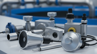
Tank level sensors differ in how they measure, and each has conditions that can affect accuracy. Ultrasonic systems measure the distance to the liquid surface without contact. Foam, vapor, turbulence, or a narrow tank opening can disrupt the returning signal. Radar also measures from above and often handles vapor and changing temperatures better, but internal supports may create false echoes. Hydrostatic sensors infer level from pressure at the tank bottom. They can work well with still liquids, though density changes affect readings. Float devices are straightforward, but moving parts can stick or wear.
Tips: Check the liquid, tank shape, and operating conditions before comparing specifications. Ask how the sensor behaves with foam, condensation, and uneven surfaces. Leave room for installation access and routine checks. A small test under real conditions can reveal problems that a brochure will not.
Record readings against a known reference during commissioning, then repeat checks at a sensible interval. That matters. For example, a sensor mounted too close to an inlet may report unstable levels when filling begins. No technology is perfect. Even a well-matched instrument can need adjustment if the process changes, and this is easy to overlook. Choose a system with clear diagnostics and a maintenance plan your operators can actually follow.
| Technology | Measurement Type and Principle | Best-Suited Applications | Key Advantages | Limitations and Selection Considerations | Installation and Maintenance Notes |
|---|---|---|---|---|---|
| Float switch | Point level; a buoyant float moves with the liquid and actuates a switch at a set level. | High- or low-level alarms, pump protection, and simple on/off control in compatible liquids. | Simple, generally economical, and does not require continuous level measurement. | Provides one or more discrete points rather than a continuous level reading. Moving parts can stick or foul in viscous, dirty, or solids-bearing liquids. | Check float material compatibility, mounting orientation, and clearance from tank walls or internal equipment. Inspect periodically for deposits or mechanical binding. |
| Hydrostatic pressure | Continuous; measures liquid pressure at a known depth and calculates level from pressure and liquid density. | Water and other liquids where density is known and reasonably stable; suitable for many deep or hard-to-access tanks. | Unaffected by surface foam and can be installed without an unobstructed view of the liquid surface. | Changes in density or temperature can create level error. Bottom deposits, blocked impulse lines, or pressure changes in a closed tank can affect readings unless the installation is designed for them. | Use a pressure arrangement appropriate to open or pressurized tanks. Confirm density assumptions and provide access for inspection or cleaning. |
| Ultrasonic | Continuous, non-contact; measures the time taken for an ultrasonic pulse to travel to the liquid surface and return. | Open or vented tanks containing liquids with a clear acoustic path and manageable surface conditions. | No wetted probe; installation and routine servicing can be straightforward for compatible applications. | Foam, turbulence, vapor, dust, condensation, or changing gas temperature can weaken or distort the echo. Internal structures may create false echoes, and a minimum measuring distance is required. | Mount above the liquid with a clear path to the surface. Review nozzle geometry, temperature range, vapor conditions, and the sensor’s blanking distance. |
| Non-contact radar | Continuous, non-contact; uses microwave signals to determine the distance to the liquid surface. | Many liquid applications, including tanks with vapor or changing process conditions, when the tank geometry and surface provide a usable echo. | Does not contact the liquid and is generally less affected than ultrasonic measurement by changes in gas temperature or pressure. | Tank internals, narrow nozzles, heavy condensation, or a weak surface reflection can complicate measurement. Correct antenna selection and echo configuration remain important. | Position to minimize obstructions and avoid filling streams where practical. Check process temperature, pressure, nozzle dimensions, and the required measuring range. |
| Guided-wave radar | Continuous; microwave pulses travel along a probe and reflect at the liquid surface. | Applications where non-contact measurement is difficult, including some narrow tanks or tanks with vapor and changing process conditions. | Guided signal can provide a defined measurement path and can measure through some vapor or surface turbulence. | The probe contacts the process and may be unsuitable where buildup, coating, corrosion, or mechanical movement is likely. Probe contact with internal structures can interfere with the signal. | Check probe type, length, mechanical support, and material compatibility. Allow clearance from tank internals and plan for inspection if deposits are possible. |
| Capacitance probe | Continuous or point level; detects changes in capacitance as liquid covers or approaches the probe. | Liquids and selected solids where the dielectric properties are suitable and consistent. | Can be applied in compact installations and, with suitable designs, in challenging tank geometries. | Readings depend on the material’s dielectric properties. Changes in composition, moisture, or buildup on the probe can cause measurement shifts or false indications. | Confirm the expected dielectric range and probe compatibility. Evaluate coating behavior and provide access for cleaning or calibration checks when needed. |
| Load cells (weighing) | Indirect continuous measurement; measures the tank’s weight and converts net contents weight to an estimated level or inventory. | Batch processes or applications where non-contact measurement is difficult and the tank can be supported on weighing sensors. | No sensor needs to contact the liquid, and the method can provide mass-based inventory information. | It does not measure the liquid surface directly. Tank supports, connected piping, agitation, vibration, and changes in liquid density can affect the relationship between weight and level. | Requires suitable mechanical support and careful installation. Account for piping forces, tank movement, tare weight, and calibration across the operating range. |
Selection note: Performance depends on the instrument design and the actual tank, liquid, installation, and operating conditions. Confirm the required measurement range, accuracy, process compatibility, safety requirements, and maintenance access before selecting a system.
Choose accuracy from the volume error your operation can tolerate, not from a sensor’s headline specification. A 10-metre-diameter vertical tank has a cross-sectional area of about 78.5 square metres. A 1 mm level error therefore represents roughly 78.5 litres, before accounting for tank shape or calibration uncertainty. API MPMS Chapter 2.2A describes manual strapping for calibrating upright cylindrical tanks; its capacity tables show why shell dimensions and reference measurements matter. Geometry matters. A horizontal tank, a dished end, or a sloped floor can make equal level changes correspond to unequal volume changes.
Check the full measurement chain: sensor accuracy, installation position, reference datum, and the tank’s calibration table. OIML R 85 sets performance and testing requirements for automatic level gauges, while ISO 4266-1 addresses automatic level measurement in petroleum storage tanks. Use these as technical references, then verify that the proposed system suits your liquid, temperature range, and operating conditions. Radar may handle vapour well, but internal beams or a narrow nozzle can complicate readings. Float systems can be simple, yet moving parts may stick. A neat specification can still mislead if it ignores foam, turbulence, or a tank’s dead zones. Check actual readings against manual measurements during commissioning; small offsets deserve investigation, even when the display looks stable.
Match sensor performance to the accuracy required and the tank geometry.
How to read this: For a 10 m liquid column, a hydrostatic level reading configured for a density of 1,000 kg/m³ has an approximate error of 0.1 m for each 1% density mismatch. This calculation assumes uniform liquid density and excludes other instrument errors. Hydrostatic systems therefore suit applications with known or compensated density. For radar or ultrasonic systems, check tank geometry for obstructions, internal structures, foam, or turbulence that could affect the measurement.
Check Installation, Connectivity, and System Compatibility
A tank level monitoring system is useful only when its sensor suits the tank and operating conditions. Measure the tank’s height, material, and access opening before choosing an installation method. Consider whether the liquid foams, leaves deposits, or changes temperature, since these factors can affect readings. A narrow steel tank may need a different mounting arrangement than an open plastic reservoir. Check the installation carefully.
Connectivity matters too. Confirm that the signal can reach the receiver from the tank location, especially inside metal enclosures or below ground. Wi-Fi may work near a building, while remote sites may require cellular or other communication options. Ask how often readings update and what happens during a connection loss. Test it on site. A coverage map alone may not reflect walls, distance, or local interference.
Tips: Check available power, mounting clearance, and cable routes before installation. Verify that the monitoring system accepts the sensor’s output and units. If possible, compare its readings with a manual measurement during setup. Small differences can be normal, but don’t ignore a persistent mismatch. Recheck the settings; they are easy to overlook.
How to Choose a Tank Level Monitoring System
Evaluate Safety, Maintenance, and Total Ownership Costs
A monitoring system should reduce exposure to tank openings, not just display a level. Check whether alarms remain clear during filling, draining, and sensor faults. Ask how the device behaves when power or communications fail. A quiet screen is not proof of safety. Small details matter: moisture at a cable entry or a poorly placed high-level alarm can undermine an otherwise capable setup. Keep routine inspections in the plan; remote readings do not reveal every leak, blockage, or damaged fitting.
Maintenance costs depend on more than the sensor price. Compare calibration intervals, replacement parts, cleaning access, battery life, and technician travel. The U.S. Department of Energy’s Operations & Maintenance Best Practices guide reports that predictive maintenance programs can reduce maintenance costs by 25–30% and downtime by 35–45% compared with reactive maintenance. These are broad industrial estimates, not guaranteed savings for a tank installation. Still, they support checking whether alerts help staff act before a fault becomes an urgent callout.
For total ownership cost, include installation, connectivity, training, repairs, and eventual replacement. NIST Handbook 135’s life-cycle-costing framework likewise looks beyond purchase price to operating, maintenance, and disposal costs. I would not assume the cheapest unit stays cheapest. A remote site may need dependable signal coverage, while a dusty process area may need more frequent cleaning. Write down those assumptions; they are often the part buyers revisit later.