
NOTICE
We use cookies to improve the user experience and analyze its performance.
Choosing Pusher Seals in 2026 requires more than matching a catalog number. The correct seal must suit the pump, shaft, fluid, temperature, pressure, and operating speed. A seal that works perfectly with clean water may fail quickly in abrasive slurry. Small details matter. Shaft runout, surface finish, spring condition, and installation cleanliness can decide the result.
Robert W. Flitney, a respected sealing technology author, offers a useful principle: “A seal is only as good as the system around it.” This idea remains highly practical for maintenance teams and equipment designers. Before selecting Pusher Seals, examine the complete operating environment. Check whether the elastomer can resist the process fluid. Confirm that the face materials can handle heat and wear. Review the spring arrangement when pressure changes frequently.
Modern buyers may also consider cartridge-style designs, upgraded carbon materials, and monitoring requirements. Yet newer technology is not automatically better. That assumption can become expensive. A simple, correctly installed pusher seal may outperform a sophisticated option in a stable application. Field experience often reveals problems that specifications miss. For example, a seal may fail after only three weeks because dry running was ignored during startup.
This guide explains how to compare Pusher Seals with greater confidence in 2026. It also examines common selection mistakes, maintenance clues, and realistic performance expectations. No seal lasts forever. Good engineering simply makes failure less surprising, less frequent, and easier to prevent.
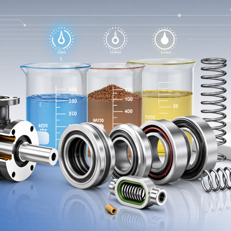
How to Choose Pusher Seals in 2026?
Pusher seals use a spring-loaded sealing face and a movable secondary seal. The secondary O-ring slides along the shaft or sleeve. This movement compensates for face wear, shaft movement, and thermal expansion. Springs maintain contact between the rotating and stationary faces. Simple in principle. Sensitive in practice.
Choose the seal around the operating conditions, not only the equipment model. Record fluid concentration, pressure, temperature, shaft speed, and start-stop frequency. Check elastomer compatibility with the process fluid. Select face materials that resist abrasion or chemical attack. ISO 21049 recommends evaluating seal design against pressure, speed, temperature, and fluid properties. These details matter because the U.S. Department of Energy reports that pumping systems can consume 25–50% of industrial facility electricity. Poor sealing can add friction, leakage, and maintenance exposure.
Tips: Inspect the shaft sleeve for scoring before installation. A sharp groove can damage the moving O-ring. Confirm spring direction and installation length. Keep faces clean; one fingerprint can create a leak path. For abrasive slurry, avoid assuming a standard pusher seal will survive. A stationary design may perform better. I would also question catalog pressure limits, because real systems often experience pressure spikes. Measure them where possible. The Energy Institute’s mechanical seal guidance supports using actual operating data instead of relying only on nominal pump conditions. Perfect selection is uncommon. Careful verification is better.
A practical comparison of pusher-seal construction, operating factors, materials, and selection criteria for rotating equipment.
| Selection Dimension | What It Means | Typical Pusher-Seal Guidance | Why It Matters | Recommended Check |
|---|---|---|---|---|
| Basic Definition | A pusher seal is a mechanical seal in which a dynamic elastomer secondary seal moves axially along the shaft or sleeve. | The moving secondary seal compensates for normal face wear, shaft movement, and small dimensional changes. | It provides a compact and widely used sealing arrangement for pumps and other rotating equipment. | Confirm that the equipment shaft, sleeve, and seal chamber are suitable for axial movement of the secondary seal. |
| How It Works | Primary sealing occurs at the rotating and stationary seal faces. The elastomer secondary seal limits leakage around the shaft or sleeve. | A spring or spring set applies closing force while hydraulic pressure helps maintain contact between the seal faces. | Stable face contact is necessary to control leakage without creating excessive friction and heat. | Review pressure, speed, temperature, lubrication, and face-loading conditions together rather than separately. |
| Typical Equipment | Commonly used in centrifugal pumps, process pumps, mixers, agitators, and selected compressors. | Suitable for many general-purpose water, chemical, utility, and process-fluid services when correctly specified. | Equipment geometry and operating conditions determine whether a standard pusher arrangement is appropriate. | Measure shaft diameter, seal-chamber dimensions, mounting length, and rotating direction before selection. |
| Primary Seal Faces | The faces form the main sliding seal and are normally manufactured from hard and/or wear-resistant materials. | Common combinations include carbon versus silicon carbide, carbon versus tungsten carbide, and silicon carbide versus silicon carbide. | Face pairing affects wear, friction, heat generation, chemical resistance, and dry-running tolerance. | Choose the pair according to fluid abrasiveness, lubrication, corrosion risk, pressure, and shaft speed. |
| Secondary Seal Material | The elastomer seals the gap between the seal components and the shaft or sleeve. | Common choices include EPDM, NBR, FKM, and FFKM, with compatibility depending on the fluid and temperature. | An incompatible elastomer can swell, harden, crack, lose elasticity, or cause leakage. | Check chemical compatibility, minimum and maximum temperature, concentration, cleaning chemicals, and exposure time. |
| Spring Arrangement | Springs provide the mechanical closing force that keeps the seal faces together. | Single-spring designs are simple; multi-spring designs distribute loading more evenly and can suit higher-performance applications. | Spring design influences face loading, balance, fouling sensitivity, and installation orientation. | Consider fluid solids, crystallization, corrosion, speed, pressure, and whether the spring is inside or outside the process fluid. |
| Balanced or Unbalanced Design | Balance describes the relationship between hydraulic pressure and the effective face area loaded by that pressure. | Balanced seals generally reduce hydraulic closing load and are often preferred for higher pressure or lower-lubricity services. | Correct balance helps limit heat and wear at the seal faces. | Use the equipment pressure and seal design limits to verify the required balance ratio; do not select by pressure alone. |
| Pressure | Pressure acts across the seal faces and can affect leakage, heat generation, and face stability. | Allowable pressure is design-specific and depends on speed, face materials, balance, temperature, and seal chamber geometry. | A seal rated for a certain pressure at low speed may have a lower allowable pressure at higher speed. | Specify normal, maximum, start-up, shutdown, and upset pressure—not only the average operating pressure. |
| Temperature | Temperature affects elastomer life, lubricant film stability, face distortion, and the physical properties of the fluid. | Temperature limits must be checked for every component, especially the secondary seal and face materials. | Excessive temperature can accelerate wear, degrade elastomers, and vaporize the process fluid at the faces. | Record operating, start-up, cleaning, and transient temperatures and compare them with material limits. |
| Shaft Speed | Rotational speed influences sliding velocity, frictional heat, vibration sensitivity, and dynamic runout. | Higher speed generally requires better face tracking, suitable balance, accurate installation, and effective heat removal. | High sliding speed can cause face overheating even when pressure is moderate. | Provide operating speed, maximum overspeed, shaft diameter, and any variable-speed drive information. |
| Fluid Lubrication | The seal faces normally rely on a very thin fluid film to reduce direct contact and control wear. | Clean, lubricating liquids are generally easier to seal than hot, volatile, gas-like, or poorly lubricating fluids. | Loss of the fluid film can produce rapid face damage and thermal cracking. | Determine viscosity, vapor pressure, solids content, crystallization tendency, and whether the liquid can flash at the faces. |
| Solids and Abrasives | Suspended particles can enter the sliding interface or damage the dynamic secondary seal. | Hard face materials, proper flushing, and a suitable spring arrangement may improve service in abrasive fluids. | Solids can scratch faces, block springs, accelerate wear, and create leakage paths. | Document particle size, hardness, concentration, settling behavior, and whether solids are present during start-up. |
| Cleanliness and Crystallization | Some fluids form deposits when exposed to air, cooling, evaporation, or temperature changes. | A seal design with protected springs or an appropriate flush arrangement may be required for crystallizing services. | Deposits can restrict axial movement and prevent the seal faces from closing correctly. | Assess drying, polymerizing, crystallizing, and sticky-fluid behavior during normal operation and shutdown. |
| Installation Tolerance | Seal performance depends on correct dimensions, perpendicularity, concentricity, surface finish, and shaft condition. | The sleeve or shaft should be free from burrs, sharp edges, deep scratches, and excessive runout. | Installation errors can damage elastomers, distort faces, or cause premature leakage. | Follow the seal drawing for setting length, end-play, runout, chamber dimensions, and tightening sequence. |
| Maintenance Needs | Pusher seals contain wear components and elastomers that may eventually require replacement. | Routine inspection should focus on leakage trend, vibration, temperature, flush flow, and equipment alignment. | Early detection can prevent secondary damage to shafts, sleeves, bearings, and seal chambers. | Establish a leakage and condition-monitoring baseline after installation and investigate sudden changes. |
| When to Consider an Alternative | A different seal architecture may be more suitable when the process is highly abrasive, gas-like, very hot, or prone to deposit formation. | Non-pusher bellows designs, cartridge arrangements, dual seals, or specialized systems may be considered depending on the duty. | No single seal type is optimal for every pressure, temperature, speed, and fluid combination. | Escalate the application for engineering review when operating limits overlap, dry running is possible, or leakage consequences are severe. |
Important: The operating ranges and material choices for a pusher seal are application-dependent. Always verify the final selection against the equipment drawing, process data, applicable safety requirements, and the seal manufacturer's technical limits.


