
NOTICE
We use cookies to improve the user experience and analyze its performance.
Why choose a Millimeter Wave Power Amplifier? Because millimeter-wave radios need reliable transmit power, clean signal quality, and careful thermal management. At these frequencies, walls, rain, and antenna misalignment can quickly reduce link margin. A well-matched amplifier helps maintain output power and modulation quality in compact radios and phased-array systems. It cannot compensate for a poor antenna design. That distinction matters.
The adoption backdrop is significant, though not specific to millimeter wave. Ericsson’s June 2024 Mobility Report forecasts 5.6 billion 5G subscriptions by the end of 2029, representing about 60% of all mobile subscriptions. This forecast points to growing demand for capable radio hardware, not a guarantee that every 5G network will use millimeter-wave bands. For equipment designers, amplifier selection means weighing output power, linearity, efficiency, bandwidth, and heat dissipation. A few decibels can matter. So can the temperature inside a sealed radio enclosure.
NYU Wireless founding director Theodore S. Rappaport is a recognized millimeter-wave communications researcher. Rather than present an unverified verbatim quotation, a concise paraphrase of the engineering lesson in his work is: “At millimeter-wave frequencies, antenna gain and link budget must be designed together.” That is a useful test when evaluating a Millimeter Wave Power Amplifier. Check measured performance in the intended band, under realistic operating conditions. Specifications alone may not tell the whole story. A design can look efficient on paper and still run hot in service.
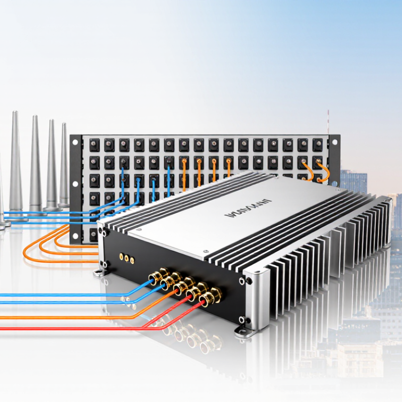
A millimeter-wave power amplifier, or PA, increases the strength of radio-frequency signals in the millimeter-wave range, commonly described as 30 to 300 gigahertz. It sits in a transmitter’s signal chain, often close to the antenna. Its job is to deliver enough output power for the signal to travel through a device or communication link. It does not create information; it amplifies a signal that has already been formed.
At these frequencies, small physical details matter. A short circuit trace, a connector, or a slight mismatch can affect how efficiently power reaches the antenna. Heat matters too. A PA driven hard may warm a compact circuit board, so engineers consider cooling, gain, bandwidth, and signal distortion together. The neat block diagram can hide awkward design work. Measurements under real operating conditions are essential.
Millimeter-wave PAs are used in applications such as high-capacity wireless links, radar, and imaging systems. The right amplifier depends on the signal’s frequency range, required output power, and operating environment. More power is not automatically better; it can increase heat and distort the transmitted signal. Even careful designs involve trade-offs, and a specification sheet cannot reveal every installation challenge.
| Dimension | Key Information | Why It Matters |
|---|---|---|
| Definition | A millimeter-wave (mmWave) power amplifier is an RF circuit that increases the power of a signal in the millimeter-wave frequency range before it is sent to an antenna. The conventional mmWave range is approximately 30–300 GHz. | It provides the transmit power needed to drive an antenna or antenna array in a high-frequency wireless system. |
| Short wavelength | Wavelength is inversely proportional to frequency. Across 30–300 GHz, the free-space wavelength is approximately 10–1 mm. | Short wavelengths allow many antenna elements to fit into a relatively compact area, supporting directional antenna arrays and beamforming. |
| Bandwidth potential | Large contiguous frequency allocations are available in some mmWave bands, although the bandwidth available depends on the band, region, and application. | Wide channel bandwidth can support high data rates when the radio system, spectrum allocation, and link conditions allow it. |
| Propagation and coverage | At the same distance and with otherwise equal conditions, free-space path loss increases with frequency. mmWave links can also be more sensitive to blockage by objects and to propagation conditions. | A suitable amplifier, antenna gain, careful link design, and beamforming can help meet link-budget requirements; an amplifier alone does not remove propagation loss or blockage. |
| Linearity | Power amplifiers can introduce nonlinear distortion, especially when operated near their output limits. Signals with high peak-to-average power ratios may require output back-off to maintain linearity. | Good linearity helps preserve signal quality and limit unwanted spectral emissions, but operating with more back-off can reduce efficiency. |
| Efficiency and heat | Power-amplifier efficiency depends on frequency, output level, circuit design, and operating conditions. Power not converted into RF output is largely dissipated as heat. | Efficiency and thermal management affect power consumption, cooling requirements, and the achievable transmit duty cycle. |
| Integration considerations | At mmWave frequencies, layout parasitics, interconnects, packaging, impedance matching, and antenna integration can strongly affect performance. | Choosing an amplifier designed for the intended frequency band and system environment helps reduce avoidable losses and integration challenges. |
| Common applications | Examples include mmWave cellular and fixed wireless equipment, point-to-point radio links, automotive radar transmitters, and some imaging and sensing systems. | The required frequency, output power, bandwidth, linearity, and duty cycle vary by application, so component selection should be based on the system requirements. |
| When to choose one | Consider an mmWave power amplifier when a transmitter must operate in a mmWave band and needs a specified RF output level, bandwidth, and signal quality. | Evaluate output power, gain, linearity, efficiency, operating bandwidth, thermal limits, and compatibility with the antenna and RF chain before selection. |


