NOTICE
We use cookies to improve the user experience and analyze its performance.
Reliable tank readings depend on more than the sensor itself. A water tank level sensor can show a steady number while the actual water surface rises and falls with filling, pumping, or turbulence. The right setup starts with the tank’s shape, the liquid, the mounting point, and the conditions around the measurement. A narrow tank, a foaming surface, or a pipe crossing the sensor’s path can all affect readings. Small details matter.
These seven tips focus on practical checks that help make monitoring more dependable. They cover sensor selection, placement, calibration, wiring, and routine inspection, with attention to common technologies such as float, ultrasonic, and pressure-based sensors. Not every method suits every installation. That is easy to overlook when comparing products by range alone. Check the manufacturer’s specifications, confirm that materials are compatible with the liquid, and test readings against a known level during setup. Then compare them again after real operating conditions have had a chance to reveal problems. A perfect reading every time is not a realistic promise; a clear process for spotting drift is. Even a careful installation can need adjustment. These guidelines are intended to help operators make informed choices and catch avoidable errors before a misleading level reading disrupts daily work.
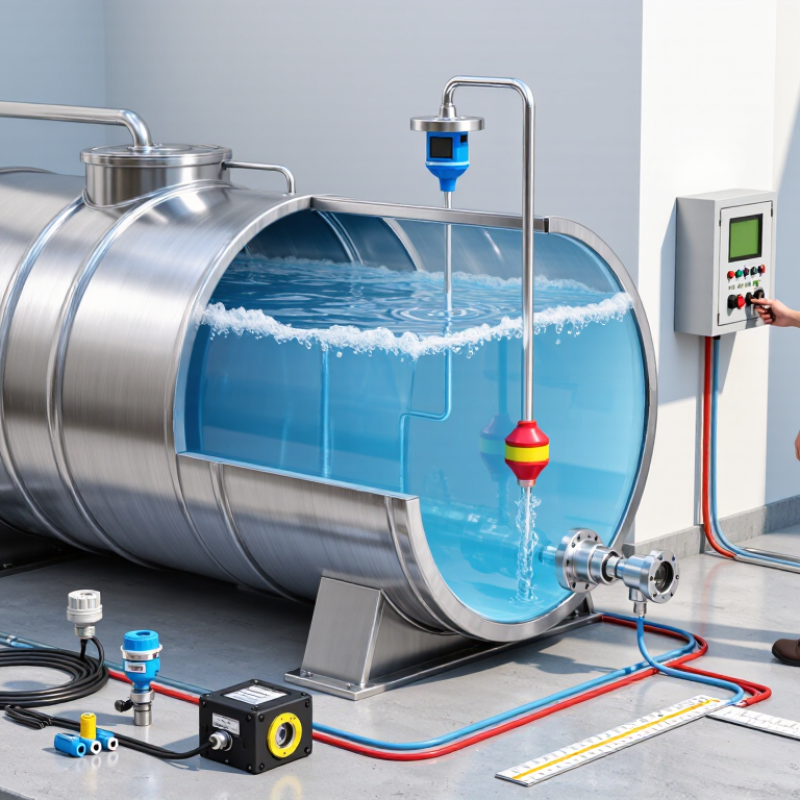
Water tank level sensors convert water height into a signal that people or control systems can interpret. The method depends on the sensor. A float rises and falls with the water, moving a switch or magnetic contact. A hydrostatic sensor measures pressure near the tank’s bottom; deeper water produces greater pressure. An ultrasonic sensor sends sound pulses toward the water and calculates the distance from the returning echo. That sounds straightforward. Each method has different limits.
With an ultrasonic sensor, foam, condensation, or a pipe in the sound path can disrupt readings. A hydrostatic sensor needs correct calibration and a secure position near the tank floor. Tank shape matters, too: a level reading does not always translate directly into the same volume in a narrow or irregular tank. Small details matter. During routine checks, compare the displayed level with a manual measurement at a few points, especially near empty and full. If readings drift, inspect mounting, wiring, and the sensor surface before changing settings. It is tempting to trust a clean digital number, but sensors still need occasional verification. A little uncertainty is better than assuming the measurement is perfect.
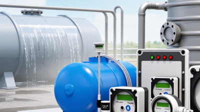
Choosing a tank level sensor starts with the liquid and tank, not the display. A vented water tank may suit a hydrostatic pressure sensor, while a non-contact ultrasonic sensor avoids direct contact with the liquid. Foam, condensation, turbulence, and internal pipes can disrupt readings. Radar may handle some of these conditions better, but tank shape and installation still matter. A neat specification sheet can mislead.
Match measurement range and accuracy to the decision you need to make. A household tank may need a low-level alarm; a process tank may require continuous readings and a stable output for control. The USGS report Estimated Use of Water in the United States in 2015 recorded 322 billion gallons per day in total U.S. withdrawals, illustrating how much water systems must manage. For smaller-scale context, the U.S. EPA estimates household leaks waste nearly 10,000 gallons annually on average. Check whether the sensor can detect meaningful level changes, and test it at the actual mounting height. Leave room for dead zones near the tank roof and bottom. I would still verify readings with a manual gauge during commissioning; installation details can defeat an otherwise suitable sensor.
Mounting position often matters more than the sensor’s advertised range. Place the sensor where the water surface stays relatively calm, away from the inlet, pump return, and tank walls. A stream of incoming water can create false readings. So can a narrow corner. For ultrasonic sensors, keep the beam clear of braces, pipes, and ladders. For submerged sensors, suspend the probe above sediment rather than resting it on the tank floor.
Follow the installation instructions for the specific sensor type. Keep the sensing face level where required, and secure cables so they cannot snag on a lid or moving equipment. Small details matter. A tilted ultrasonic unit may measure a sloping surface, while a hydrostatic probe can shift if its cable is left loose. Leave enough access for inspection, but protect electrical connections from moisture. After mounting, compare the displayed level with a measured water depth at a known point. Test again when the tank is partly full; one calibration point may hide an error. It is easy to assume a steady reading means a correct one. It may not. Check for condensation, turbulence, and buildup during routine maintenance, and record any adjustments.
Accurate tank alerts begin with a dependable reference. Compare the sensor reading with the actual water depth at two or three known points, such as a nearly empty tank and a marked halfway level. Record each value and check whether the readings change consistently across the tank’s usable range. For ultrasonic sensors, keep the measurement path clear of pipes, ladders, and turbulent inlets. For other sensor types, follow the relevant calibration instructions. Small setup details matter.
Tips: Recheck calibration after moving the sensor, changing its mounting height, or cleaning the tank. Use a measuring tape and note the date, water depth, and displayed reading. Don’t adjust the scale to hide a sudden mismatch; investigate the cause. It may be buildup, a loose connection, or a changed reference point.
Set alert levels around real operating needs, not convenient round numbers. A low-level warning should leave enough water for normal use and time to arrange a refill. A high-level alert should activate before water reaches the overflow, allowing for sensor delay and waves from incoming water. Add a short delay or deadband if readings flicker near a threshold. Test each alert by safely simulating the level, then confirm the message reaches the intended person. Even careful calibration can drift, so review readings periodically. A tidy chart can still miss an awkward tank shape.
Calibrating Readings and Setting Alert Levels
This illustrative 200 cm tank profile shows calibrated level readings over 12 hours. Set alert thresholds to match the tank’s usable capacity and operating needs; here, alerts are shown at 40 cm (low) and 180 cm (high). Check sensor readings against known reference levels during calibration, and recalibrate if measurements drift.
A water tank level sensor can become less reliable when residue, condensation, or loose wiring affects its readings. Inspect the sensor and its cable during routine maintenance, looking for corrosion, cracks, or moisture around connections. Clean buildup gently using a method suitable for the sensor type; abrasive tools can damage sensitive surfaces. For ultrasonic sensors, check that foam, spray, or an object inside the tank is not blocking the sound path. Small details matter.
Verify readings against a careful manual measurement when the tank is stable and safe to access. Record both values, the date, and the tank level. A consistent difference may indicate that the sensor needs adjustment, but first check its mounting position and settings. Readings can also vary with temperature, tank shape, or turbulence, so one comparison may not reveal a real fault. I have seen a quick check look convincing, then fail when the water level changes.
Tips: Compare readings at low, middle, and high levels when practical. Repeat each check under similar conditions, and keep a simple log. If the gap grows or readings jump unexpectedly, inspect the installation before changing calibration settings. Use the sensor’s instructions for model-specific checks.
| Tip | Maintenance Focus | What to Do | How to Verify Accuracy | Suggested Check Timing |
|---|---|---|---|---|
| 1 | Inspect the sensor and tank area | Look for physical damage, loose fittings, corrosion, leaks, or buildup near the sensing point. Check that the sensor remains securely mounted in its intended position. | Compare the installation with the sensor instructions and record any changes that could affect the measurement, such as movement, deposits, or a changed tank configuration. | During routine site inspections and after maintenance, impact, or unusual readings. |
| 2 | Clean sensing surfaces carefully | Remove deposits from wetted probes or other accessible sensing surfaces using a method and cleaning agent compatible with the sensor materials and the water. Do not scrape or use chemicals unless the manufacturer permits them. | Before and after cleaning, compare the displayed level with a safe independent level reference. A change after cleaning may indicate that buildup was affecting the measurement. | Set the interval based on water quality and observed fouling; inspect more often where scale, sediment, or biological growth is present. |
| 3 | Check mounting and alignment | Confirm that floats move freely, probes remain at their specified depth, and non-contact sensors have a clear sensing path. Keep the sensing area clear of obstructions where the sensor design requires it. | Observe readings at more than one known level, if practical. Check that the displayed level changes consistently as the water level rises or falls. | After installation or adjustment, and whenever readings appear stuck, erratic, or inconsistent. |
| 4 | Inspect wiring and connections | Check accessible cables, connectors, seals, and enclosures for moisture, wear, corrosion, or loose connections. Follow electrical isolation procedures before handling wiring. | Compare the sensor output or controller input with the expected signal range specified for that system. Investigate intermittent readings or signal dropouts. | During scheduled electrical inspections and after water ingress, vibration, or cable work. |
| 5 | Compare with an independent reference | Use a suitable reference, such as a calibrated dipstick or another verified measurement method, where it can be used safely. Measure from the same datum and account for tank geometry. | Record the sensor reading and reference reading at the same time and water level. Repeat at several levels where practical; investigate differences beyond the system’s specified tolerance. | At commissioning, after sensor work, and at a documented interval appropriate to the application and required accuracy. |
| 6 | Check scaling and tank dimensions | Confirm that the configured tank height, zero point, measurement units, and any level-to-volume conversion match the actual tank. Irregular tank shapes may need a measured conversion table. | Check the displayed level at known reference points and compare any volume display with the tank’s documented capacity data. Do not assume volume changes linearly with level in every tank. | After controller changes, tank modifications, sensor relocation, or unexplained volume discrepancies. |
| 7 | Test alarms and record results | Test high- and low-level alarms and related outputs using the approved test procedure. Keep a log of readings, cleaning, adjustments, reference checks, and any corrective work. | Verify that alarms activate at their configured setpoints and that the displayed reading agrees with the independent reference within the required tolerance. | At commissioning and the site’s scheduled functional-test interval; retest after changes or repairs. |
Safety and accuracy note: Follow the sensor and site procedures for isolation, cleaning, and testing. Never enter a tank or use an unsafe access method to obtain a reference measurement. Check the applicable equipment specifications for tolerances and calibration requirements.